
Analysis of DC Motor using MATLab
By Aravind H
Project Objective
The objective of this project is to analyze a DC Motor which is available in the market using the Torque-Speed Characteristics plot and determining back EMF, using MATLab software.
Introduction
DC Motors are used in my places because of their many advantages like, DC motors are free from harmonics, Wide range of speed control, etc. Due to these advantages they are used in many traction based applications like cranes, elevators, etc. The analysis of these motors are very important because of their heavy use in such traction based applications.

Fig 1. A DC motor being used in an elevator.
Technologies Involved
DC Motor
A DC motor converts electrical energy to mechanical energy.
General working Principle:
A DC motor operated according to the principle of electromagnetism given by Faraday. The law is stated as below:
“ A current carrying conductor when placed in a magnetic field will experience a force.”
This force that the conductor faces can be derived using the below equation:
F = B*I*L * SIN(Ө)
Where
F = Force
B = Magnetic flux density (Strength of Magnetic Field)
I = Current passing through the conductor
L = Length of the conductor
Ө = Angle that the Conductor makes with the Magnetic field.
The direction of this force is determined with the help of Fleming’s Left hand rule.

Fig 2. Fleming’s Left hand rule.
There are 2 main parts of a DC machine, Field Winding and Armature winding. The field winding is and the armature winding is supplied with the DC current, sometimes Armature winding is exchanged with Permanent Magnets.
Construction:
Yoke:
It is the outer part of the DC motor, which provides support to field poles, acts as a cover and it is the path through which pole flox travels.
Field Poles:
It consists of Field windings, pole core and pole shoe. Pole core and shoe are laminated to reduce eddy current. Pole core is used to support the field winding, pole shoe is used to spread the flux evenly and field winding produces North and south pole using the current passed through it.
Armature:
It is the part of the rotating element of the machine. It consists of core and armature winding. This core houses the armature winding. Armature windings form a coil to produce electromagnetism.
Commutator:
An alternating emf is induced in the armature coils of the DC machine and to provide direct current to the armature we use commutators. Commutators are made up of copper and are separated from each other using Mica sheets. Armature coils are connected to each commutator segment.
Brushes:
Brushes are made up of carbon or electrographite material, as they can conduct electricity. They pass the DC supply from an external source to the Commutator. As they rub on the commutator, they can produce spark, which is the main drawback of DC motors.
Types of DC Motor:
There are different type of DC motors based on the method of connecting the field winding with the armature:
-
DC Shunt Motor
As the name suggests the windings in this type of motor are connected in parallel to each other. Both the Field and Armature winding have the same supply voltage.
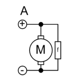
Fig 3. DC Shunt Motor
-
DC series Motor
In this motor both the field and armature winding are connected in series. Hence the field current is equal to the armature current. It is never run in no-load conditions as the speed is very high at small load current.

Fig 4. DC Series Motor
-
Compound DC motor
In this type of motors, we have both series and shunt field windings. At light loads, the motor behaves like a shunt motor and at high loads, the motor behaves like a series motor.

Fig 5. DC Compound Motor
Involved Software
MATLab
Matlab is a software which uses programming and numeric computing to analyze data, create models and develop algorithms.
Step wise Implementation
Using the below Code to analyze the data:
Analyzing data for the below motors, which are made by Moog Components group(The link to data sheet is given in the link section below) :

1. C23-L33-W10
DC input voltage(V) = 12
Rated speed in rad/sec(Sp) = 492
Armature current in A(Ia) = 4.75
Torque Constant in Nm/A(Kt) = 0.0187
Voltage Constant (Back Emf constant) in Vs/rad (Ke) = 0.0191

2. C23-L40-W10
DC input voltage(V) = 12
Rated speed in rad/sec(Sp) = 241
Armature current in A(Ia) = 4.9
Torque Constant in Nm/A(Kt) = 0.0342
Voltage Constant (Back Emf constant) in Vs/rad (Ke) = 0.0342

3. C23-L45-W10
DC input voltage(V) = 12
Rated speed in rad/sec(Sp) = 204
Armature current in A(Ia) = 5.8
Torque Constant in Nm/A(Kt) = 0.0428
Voltage Constant (Back Emf constant) in Vs/rad (Ke) = 0.0430
4. C23-L50-W10
DC input voltage(V) = 12
Rated speed in rad/sec(Sp) = 168
Armature current in A(Ia) = 5.1
Torque Constant in Nm/A(Kt) = 0.0517
Voltage Constant (Back Emf constant) in Vs/rad (Ke) = 0.0517

5. C23-L55-W10
DC input voltage(V) = 12
Rated speed in rad/sec(Sp) = 141
Armature current in A(Ia) = 5.6
Torque Constant in Nm/A(Kt) = 0.0620
Voltage Constant (Back Emf constant) in Vs/rad (Ke) = 0.0620

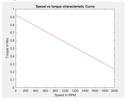
Conclusion
As you can see from the above graphs of different models of DC motors provided by Moog Components group, the slope of torque vs speed chara is downward slope. This downward slope is a characteristic of a DC motor, this is because the DC motor produces high starting torque at low speed, which shows that these motors are good for traction based applications.
Link
https://docs.google.com/document/d/1MtCEzhv4_p8lfUFzK2Tlju9hIzQOBT-ir29PkE39wYM/edit?usp=sharing
Permanent Magnet DC Brush Motors Technical Data Sheet (moog.com)


Why Choose DIY Course
 Course work & interactions are 100% online.
Study at the time and place that suits you.
24/7 access to course material.
Learn from world-class experts in their field.


0 responses on "Analysis of DC Motor using MATLab"