- Discuss about the equivalent circuit network of induction motor MATLAB model.
- 3 phase, 50 Hz induction motor, represented by equivalent circuit constants X1 = X2 = 0.1 ohm and R1 = R2 = 0.2 ohm is operated at half of rated voltage and frequency. Calculate the ratio of starting torque at half voltage & frequency to rated values.
- Make a MATLAB script file which will plot speed torque characteristics for frequency control method.
SOLUTION-
- Induction Motor Matlab Model>
- Library:
- Powertrain Blockset / Propulsion / Electric Motors
-
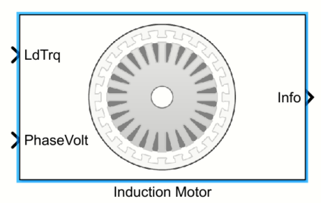
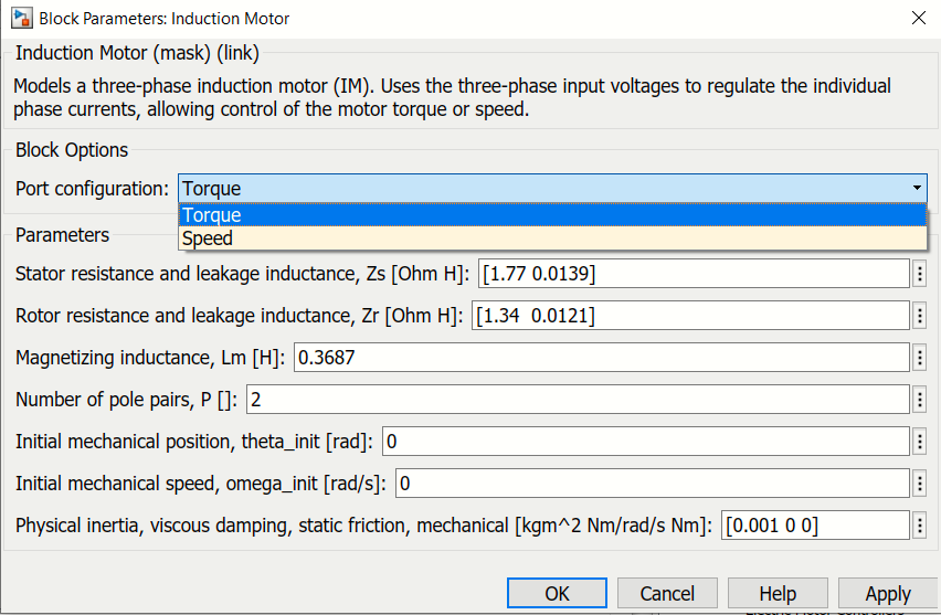
- Model Description> The Induction Motor block implements a three-phase induction motor. The block uses the three-phase input voltages to regulate the individual phase currents, allowing control of the motor torque or speed.
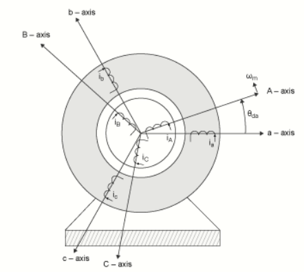
Three-Phase sinosoidal Model Electrical System> The block implements equations that are expressed in a stationary rotor reference (qd) frame. The d-axis aligns with the a-axis. All quantities in the rotor reference frame are referred to the stator.
Working> An Induction Motor is a well-known device which works on the principle of transformer. So it is also called the rotating transformer. That is, when an EMF is supplied to its stator, then as a result of electromagnetic induction, a voltage is induced in its rotor. So an Induction motor is said to be a transformer with rotating secondary. Here, primary of transformer resembles stator winding of an induction motor and secondary resembles rotor.
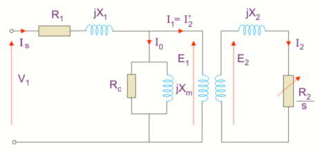
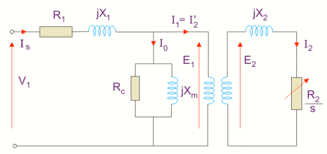
Equivalent Circuit> The equivalent circuit of any machine shows the various parameter of the machine such as its Ohmic losses and also other losses.The losses are modeled just by inductor and resistor. The copper losses are occurred in the windings so the winding resistance is taken into account. Also, the winding has inductance for which there is a voltage drop due to inductive reactance and also a term called power factor comes into the picture. There are two types of equivalent circuits in case of a three-phase induction motor- Circuit 1>
The induction motor always runs below the synchronous or full load speed and the relative difference between the synchronous speed and speed of rotation is known as slip which is denoted by s. Slip(s)=(Ns-N)/Ns Synchronous speed(Ns)=120f/P
Ws)=2*π*Ns Where f is the supply frequency & P is the no of pole.
Where, R1 is the winding resistance of the stator.
X1 is the inductance of the stator winding.
Rc is the core loss component.
XM is the magnetizing reactance of the winding.
R2/s is the power of the rotor, which includes output mechanical power and copper loss of rotor.Circuit 2> If we draw the circuit with referred to the stator then the circuit will look like-
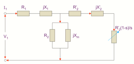
Where, R2’ is the rotor winding resistance with referred to stator winding.
X2’ is the rotor winding inductance with referred to stator winding.
R2(1 – s) / s is the resistance which shows the power which is converted to mechanical power output or useful power. The power dissipated in that resistor is the useful power output or shaft power.Now,
Zeq=(R1+R’2(1-s)/s)+j(X1+X’2)
Is=V1/Zeq
Putting the value of Zeq we get,
Is=V1/[(R1+R’2(1-s)/s)+j(X1+X’2)] Is=lIsl=V1/[(R1+R’2(1-s)/s)^2+j(X1+X’2)^2]
P=V1IsCosΦ2 =(V1^2)(R’2(1-s)/s)/[(R1+R’2(1-s)/s)^2+(X1+X’2)^2]
Torque equation is given by,
T=P/Ws
T=(V1^2)(R’2/s)/Ws[(R1+R’2/s)^2+(X1+X’2)^2]
The above equation is the torque equation of an induction motor.
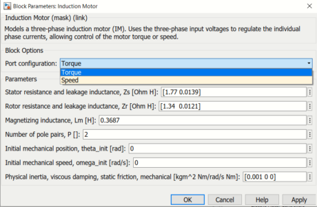
- For an induction motor Torque calculation, the parameters are following>
R1=Stator resistance
R2=Rotor resistance
X1=Stator inductance
X2=Rotor inductance
V1=Voltage Applied
Ns=Synchronous Speed
Ws=Angular speed
P=Number of poles
f=Supplied frequency
Ph=No of phase
Given values of these parameters are> R1=R2=0.2 ohm
X1=X2=0.1 ohm
V1=V/2 (half of the rated voltage)
f’= f/2 (half of the rated frequency)
Formula>
Ws=2*π*Ns
Ns= 120*f/P
At half of the rated frequency>
Ns=120 *f/2P
=1/2*(120*f/P)
Now 120*f/P=2*Ns=Ns’
or, Ws=2*π*Ns’
=2*π*2*Ns
or Ws’=Ws/2=2*π*Ns
Starting torque at rated voltage and frequency>
T=Ph*(V1^2)(R2)/Ws[(R1+R2)^2+(X1+X’2)^2]
=3*(V^2)(0.2)/Ws[(0.4^2)+(0.2^2)]
Tr=3*(V^2)/Ws……….(i)
Starting torque at half of the rated voltage and frequency>
T=Ph*(V1^2)(R2)/Ws[(R1+R2)^2+(X1+X’2)^2]
=3*(V/2)^2(0.2)/(Ws/2)[(0.4^2)+(0.2^2)]
Thr=3*(V^2)/2*Ws…….(ii)
Comparing equation (i) and (ii) we get>
(Thr/Tr)=[3*(V^2)/2*Ws]/[3*(V^2)/Ws]
=1/2
=0.5
Therefore the ratio of starting torque at half voltage & frequency to rated values will be 0.5.
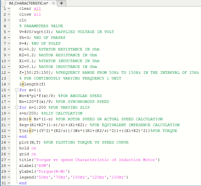
3.MATLAB Script>
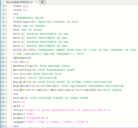
EXPLANATION>
Here in this matlab script file all the parameters for speed and torque equation is provided. After that 5 variable frequency is provided with a fixed interval. Then for calculatiing Angular speed and synchronous speed a function is defined which will varry the frequency by continously increasing its value of 1 unit. Then slip is also varried in the range of 1 to 200. After that all the inputs are given in the Speed and Torque equations. By which we can plot the Characteristic curve of Speed vs Torque.
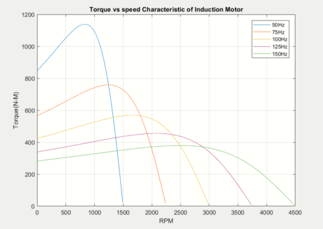
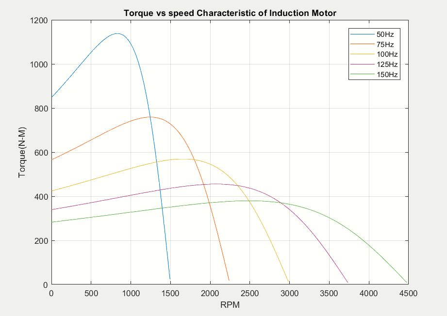
MATLAB Simulation>
-
EXPLANATION>
Torque Speed Characteristic is the curve plotted between the torque and the speed of the induction motor. As we can see the nature of the curve is like that as the speed is increasing the torue is also increasing upto a perticular point and after that as the speed is incresing further but the torque is reducing and become zero at max speed, the point is called the breakdown or peak torque point. Moreover in the variation of frequency as the frequency is increasing the speed is increasing but the maximum torque is reducing.
What is the future of induction motors?
Induction motors have been widely used in various industries for many years due to their reliability, robustness, and low cost. As technology advances, the future of induction motors looks promising, and they are expected to continue to be an important component in various applications. Here are some potential developments in the future of induction motors:
- Energy efficiency: The demand for energy-efficient motors is increasing, and induction motors are no exception. Advances in motor design and control technology are making it possible to improve the efficiency of induction motors, which will reduce energy consumption and save costs.
- Sensorless control: Currently, induction motors require sensors to measure motor parameters, such as speed and position, for control purposes. However, advances in control algorithms are making it possible to control induction motors without the need for sensors, reducing the cost and complexity of motor control.
- Condition monitoring: The ability to monitor the condition of motors in real-time is becoming increasingly important, as it can help prevent motor failures and optimize maintenance schedules. Advances in sensor technology and data analytics are making it possible to monitor the condition of induction motors more accurately and reliably.
- Integration with the Internet of Things (IoT): Induction motors can be integrated with IoT technology to enable remote monitoring, control, and maintenance. This will improve efficiency, reduce costs, and increase uptime by providing real-time data on motor performance.
- Use in renewable energy systems: Induction motors are well-suited for use in renewable energy systems, such as wind turbines and solar panels, due to their robustness and low cost. As the demand for renewable energy grows, induction motors will play an important role in the development of these systems.
Overall, the future of induction motors looks bright, with advancements in energy efficiency, control, condition monitoring, and integration with IoT technology. As such, they will continue to be an important component in various applications for years to come.
What are the job opportunities in induction motors?
There are several job opportunities related to induction motors, and they can be found in various industries such as manufacturing, engineering, and renewable energy. Here are some job roles related to induction motors:
- Electrical Engineer: Electrical engineers are responsible for designing, developing, and testing electrical systems, including induction motors. They work on the design and development of motor control systems, including hardware and software components.
- Manufacturing Engineer: Manufacturing engineers are responsible for optimizing manufacturing processes, including the production of induction motors. They work on the design and implementation of manufacturing processes, quality control, and testing of the finished product.
- Maintenance Technician: Maintenance technicians are responsible for the maintenance and repair of induction motors. They perform routine maintenance, troubleshoot issues, and replace defective components as necessary.
- Sales Engineer: Sales engineers are responsible for selling products, including induction motors, to customers. They work closely with customers to identify their needs and provide solutions that meet their requirements.
- Renewable Energy Engineer: Renewable energy engineers are responsible for designing and developing renewable energy systems, including those that use induction motors. They work on the design and development of systems that use induction motors for wind turbines, solar panels, and other renewable energy applications.
- Research and Development Engineer: Research and development engineers are responsible for developing new technologies and improving existing ones, including those related to induction motors. They work on the design and development of new motor technologies, control systems, and other related components.


Why Choose DIY Course
 Course work & interactions are 100% online.
Study at the time and place that suits you.
24/7 access to course material.
Learn from world-class experts in their field.